Pipeline Spheres

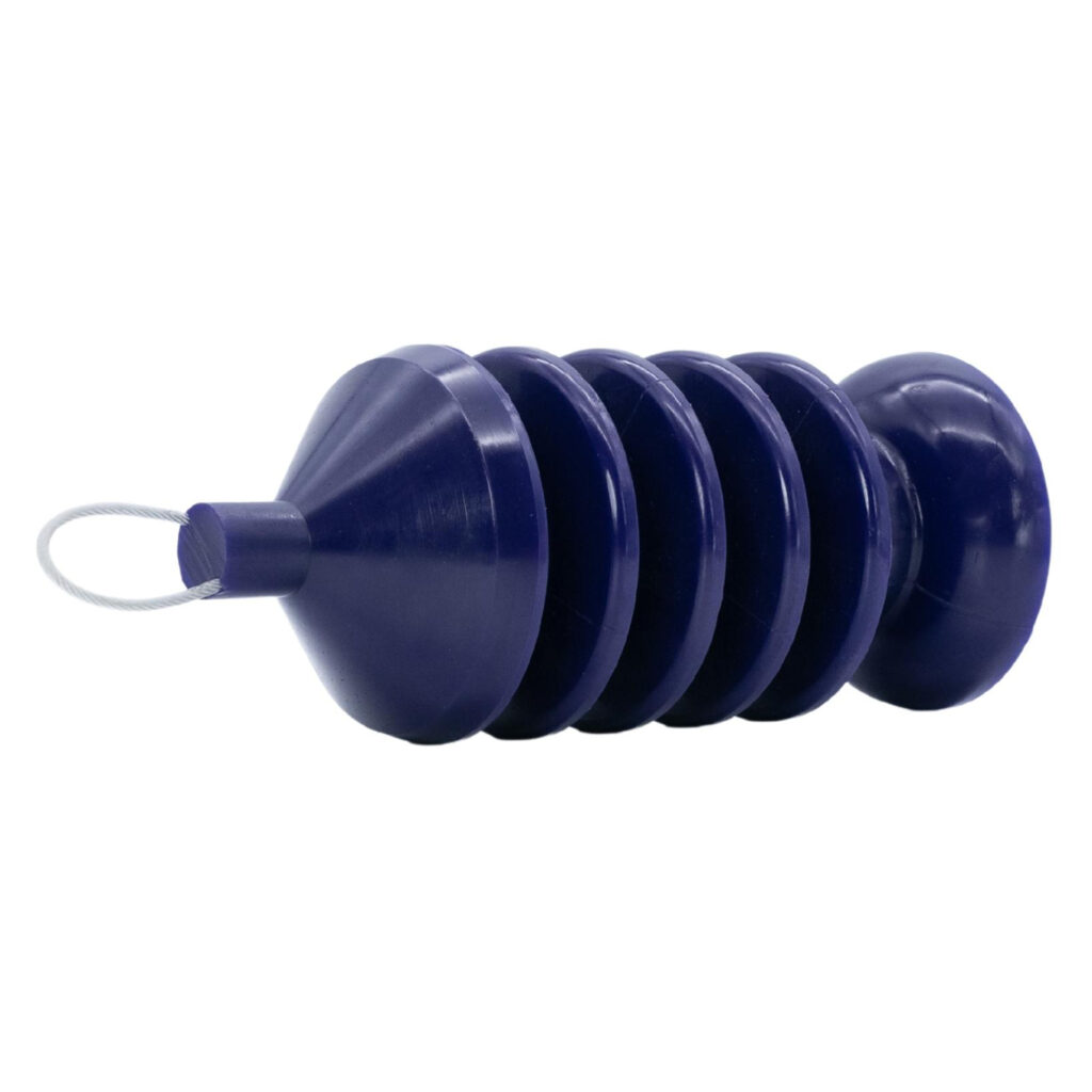
Inline’s polyurethane spheres are ideal for removing liquids from wet gas systems, meter proving, measurement services, product separation, hydrostatic line testing and wax control in crude oil pipelines. Our spheres are manufactured with the highest quality polyurethane using a unique process that allows the sphere to be seamless and eliminating the possibility of seam splitting or delaminating during service. This manufacturing process also allows for the valve bodies to be firmly embedded in the sphere wall which prevents leakage around the valve. Inline’s offers both inflatable and solid designs in a variety of sizes and durometers of hardness.

RESOURCES

CATEGORIES:

FEATURES & BENEFITS

  • One piece, seamless construction
  • Greater flexibility for adapting to changing line conditions
  • Lasting service in the worst pipeline conditions
  • Reliable performance in high-pressure gas service and sour crude oil environments
  • Better abrasion and blister resistance
  • More consistent wall thickness offering truer diameters, uniform wear and constant wall contact in proving and pipeline operations
  • Solids, 2” – 6” Diameter
  • Inflatable Sizes, 6” – 42” Diameter
  • Truer diameters for meter prover operations
  • Several durometer hardnesses
  • We will fill and size inflatable spheres
  • Sizing rings available

SPECIFICATIONS

SIZEA INCHESB INCHESWEIGHT LBS.LINE OR PROVER
2″2Solid.23BOTH
3″3Solid.6BOTH
4″3.9Solid2.3BOTH
4″4Solid2.3BOTH
4″4.1Solid2.3BOTH
4″4.2Solid2.3BOTH
6″5.91.55BOTH
6″6.11.55BOTH
6″6.21.55BOTH
6″6.41.55BOTH
8″7.71.759.5BOTH
8″81.759.5BOTH
8″8.21.759.5BOTH
8″8.31.759.5BOTH
10″9.5220BOTH
10″10220BOTH
10″10.3220BOTH
10″10.5220BOTH
12″11.7235BOTH
12″12235BOTH
12″12.3235BOTH
12″12.7235BOTH
14″132.2555BOTH
14″13.32.2555BOTH
16″14.32.568BOTH
16″15.32.568BOTH
18″17.32.597BOTH
20″19.33120BOTH
22″213140BOTH
24″233190BOTH
30″28.53315BOTH
30″29.33315BOTH
36″34.53506BOTH
42″41.253817BOTH

RELATED

Simple Pigging System with Drop-Out

This animation demonstrates an Inline Services VIPRS pig running through a line where a JB pig receiver unit is present. Before the pig is placed in the line the valve has been closed so that no product is present behind the VIPRS pig. As the pig moves through the line the inside of the pipe is cleaned and excess product is pushed through to the destination. Once the pig triggers the magnetic pig senor and reaches the JB receiver unit, the unit is removed with the pig inside. Once the pig is removed, the receiver is returned to the pipe.

Simple Pigging System Closure

This animation demonstrates a simple pigging system closure. Inline’s VIPRS pig is positioned in the launcher as the product is run through the pipeline. At the end of the product run, the VIPRS pig is launched to remove all product from the line. The pig will trigger the indicator to alert that the pig has reached the end of the line.

Bi-Directional Pigging

This animation demonstrates Bi Directional Pigging. Inline’s VIPRS pig positioned in the launcher as product is run through the pipeline. At the end of the product run, the VIPRS pig is launched to remove all product from the line. When the VIPRS pig reaches the JB receiver, the propelling media is turned-off. When this happens the VIPRS pig is resting at the jail bar in the JB receiver; propellant is used on the receiver side of the pig to return it to the launcher.

Automated CIP System

This animation demonstrates a fully automated VIPRS bi directional pigging process system with CIP. Inline’s VIPRS pig is first positioned in the pig launcher. The product is pumped from the storage tank to the destination. The VIPRS pig is then launched to push the remaining product to the destination and captured in the VIPRS wash chamber at the destination station. Next, the CIP solution is pumped through the line to wash the chamber and pig. Finally, the pig pushes the CIP solution out of the piping and leaving the pig clean and ready for the next product run.